Head Up Display
The head up display (HUD) system is designed to provide the crew with a display of flight-critical information with minimum transitions from eyes out the window (head up).
Declutter
| Level | Result |
|---|---|
| 0 | Nominal |
| 1 | Blanks runway symbol |
| 2 | Blanks airspeed scale, altitude tape, glideslope indication, attitude scales. Forces up digital airspeed and altitude |
Note: In F·SIM, the declutter level is automatically set to 1 when altitude is lower than 10000ft and visibility is good enough for the runway to be seen. Declutter level is automatically set to 2 when altitude is lower than 4000ft.
Display Description
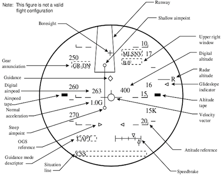
The HUD symbology has been designed to provide the pilot with the information required to accomplish precise and repeatable orbiter approach and landings.
Boresight
The boresight symbol is a small cross (+). Its position in the display is fixed and depicts an extension of the orbiter X-axis. Pitch attitude can be determined by reading the boresight symbol position with respect to the pitch attitude lines.
Runway Symbology
The runway symbol consists of a four-line drawing of a runway depicting the threshold, sides, and end. The symbol also includes the outer and inner glide slope (OGS, IGS) aim points depicted as small circles and joined together by a line representing the runway and centerline extended. All of the elements of the runway symbol are perspectively drawn so as to appear proportionally one to one with the real-world scene whenever that scene is within the HUD FOV.
Digital Altitude
Digital altitude displays altitude to main wheels with respect to the runway. If an R is displayed after the digits, the altitude is radar.
Altitude Tape
The altitude tape consists of a fixed rectangle against which a moving scale of altitude of the main gear height above the runway is read.
Glide Slope Indicator
The glide slope indicator (GSI) is a triangle facing the altitude scale. The symbol is free to move with respect to the altitude scale. When no error exists between the guidance computed reference trajectory altitude and actual altitude, the triangle will lie exactly adjacent to the altitude rectangle. The GSI is termed a ”fly to” indicator. When actual altitude is above the reference trajectory altitude, the triangle will be below the rectangle and vice versa. To correct the altitude error, the pilot must fly the orbiter towards the triangle.
The scaling of the altitude reference monitor varies with altitude.
Flight Director/Velocity Vector
Prior to TAEM prefinal, the HUD has a flight director symbol fixed in the center of the PDU. The flight director symbol consists of a small square with wings and a tail. This symbol can be used with the guidance diamond to null guidance-commanded errors.
At TAEM prefinal, the flight director symbol automatically releases and becomes a velocity vector. A 5-sec fader has been incorporated to smooth the transition from flight director to velocity vector.
The velocity vector (V) symbol consists of a small circle with wings and a tail to pictorially represent the orbiter. The wings of the symbol always remain parallel to the wings of the orbiter during maneuvering flight. A line-of-sight projection from the pilot’s eye through the symbol depicts the instantaneous flight path of the orbiter. Precise adjustments of flight path can be accomplished as required by overlaying the V symbol on the desired aim point. Wind effects are readily apparent as manifested by the V symbol drifting left/right or up/down on the PDU. Note that the guidance diamond, OGS reference triangles, and digital airspeed (DAS)/altitude all move relative to V position on the HUD. This results in a consistent cross-check on final approach for any wind condition.
The V symbol is constrained to remain in the HUD total field of view (TFOV). When a large sideslip angle or angle-of-attack exists which forces the symbol to the limits of the TFOV, further travel of the symbol in the limited direction will be precluded, and an X will be superimposed in the center of the symbol. The X will remain superimposed in the symbol until the sideslip angle or velocity which drove the symbol to the TFOV limits is reduced.
Flight Path/Pitch Attitude Reference Scales
The flight path/pitch attitude scales display 5° increments above and below the horizon. Lines above the horizon are solid with end ticks pointing down toward the horizon. Lines below the horizon are dashed with end ticks pointing up toward the horizon. The numerical value of the scale line is displayed at the right end of each line in the elbow formed by the line and its horizon direction mark. The lines are positioned in the display by reference to the horizon line.
The horizon line and flight path/pitch attitude scales are roll and pitch stabilized so that orbiter attitude changes cause them to rotate and translate in the FOV. The center of rotation of the entire symbol is about the center of the HUD FOV.
The flight path/pitch attitude scales can also be used to determine angle-of-attack, which can be observed as the absolute value of the scale difference between the boresight and the velocity vector.
Speedbrake
The speedbrake symbol consists of a horizontal scale and two opposed pointers. The upper pointer indicates speedbrake position and the lower pointer indicates speedbrake command.
OGS Reference
The OGS reference symbol consists of two opposed triangle indices. The indices are roll stabilized so that a line drawn between them will always remain parallel to the horizon.
Normal Acceleration
Normal acceleration is displayed below and outboard of the left wing of the velocity vector. The symbol digits will flash when Nz exceeds the load limit (2.0g).
Airspeed Scale/Tape
The airspeed scale consists of a fixed rectangle against which a moving scale of equivalent airspeed is read. Numerics are provided every 10 knots. A tick mark is used to define 5-knot increments between the numerics. The numerics roll on/off the scale as airspeed changes.
Digital Airspeed
Declutter level 2 forces the DAS to be displayed on the HUD. DAS is displayed above and slightly outboard the left wing of the velocity vector. The DAS moves with the velocity vector throughout the FOV. At touchdown, (WOWLON flag set), the DAS is repositioned to the upper left corner of the boresight. When WONG has occurred, a G is displayed in front of the DAS to indicate groundspeed.
Guidance
The guidance symbol is a diamond. Its position in the display depicts the direction to which the orbiter must be flown to satisfy the GPC-derived guidance solution. When the flight director symbol overlays the guidance diamond, the guidance error is zeroed. The symbol is constrained to remain in the TFOV and when limited will flash.
Flare Reference
At approximately 3800 ft, a set of flare reference indices identical in shape and size to the OGS reference indices will appear in the bottom of the HUD and move up to merge with the OGS indices. When the two sets of indices (OGS and flare) merge, they become a single set that continues to display the flight path angle requirements of the preflare-to-landing maneuver. By maintaining the velocity vector wings precisely in line with the flare indices throughout the preflare to final flare, the desired flight path angle profile will be tracked.
NAV altitude is the source of data for the flare reference indices.
Horizon
The horizon line consists of a solid line with a 4° gap in the center. It is positioned with respect to the local horizontal.