Introduction
Although the Space Shuttle Main Engines (SSME) are among the most powerful rocket motors ever built, they are only used during ascent. The orbital maneuvering system (OMS) and the reaction control system (RCS) are used to initiate re-entry and to control the orbiter in the very thin air respectively, where the aerodynamic control surfaces have no effect. But once the air gets more dense, the orbiter is basically a glider, i.e. with about 200,000 lbs a rather heavy glider (the astronauts call it a "flying brick".)
The entire re-entry is flown at hypersonic and supersonic speeds (the speed at re-entry interface is about Mach 20, i.e. twenty times the speed of sound.) In this flight phase the orbiter is controlled by its onboard digital autopilot (DAP.) As soon as the speed drops subsonic, the pilot can take over control using Control Stick Steering (CSS). Note that the RCS-jet and aerosurface actuators are still controlled by the DAP. The pilot's commands are merely an input to the DAP. This is called "fly by wire", and the space shuttle was in fact the first aircraft that utilized a fly-by-wire system with a digital autopilot. The speed brake usually remains under computer control, but the landing gear has to be armed and deployed manually.
Terminal area energy management
The flight phase between after atmospheric re-entry and wheels-stop is called terminal area energy management (TAEM). During this atmospheric flight the orbiter is controlled just like any ordinary airplane, using its large control surfaces: Its elevons (combined elevators and ailerons) and its rudder, which also functions as a speed-brake. Since the orbiter is an unpowered glider, it has to use the energy it has (its altitude and speed) to reach the Shuttle Landing Facility (SLF) runway. Of course there's a huge safety margin, so during the TAEM phases the excess energy has to be dissipated . This is done by flying the orbiter past the runway in an altitude of about 40000ft followed by an (approx.) 270 degree turn called the Heading Alignment Cone (HAC). After the HAC the orbiter is aligned with the runway centerline and glides down the so called outer glideslope at an angle of 20 degrees and an equivalent airspeed of about 300 kts (this is about 10 times as steep and twice as fast as a normal airliner approach!). At 1800 ft above ground level the pilot pulls up in what is called the pre-flare maneuver, aligning the orbiter with the 1.5 degree steep inner glideslope. At 2000 feet the gear is armed and at 300 feet it is deployed. At about 30 feet, the pilot pulls up to a pitch angle of about 8 degrees (the final flare), and the orbiter should touch down right on the runway centerline, within the nominal touchdown zone, an airspeed of about 200 kts, and a vertical speed lower that 6 feet per second. At 180 knots the pilot derotates the vehicle and the nosewheel touches down. The nose gear strut is shorter than that of the main gear, so the huge wings are pitched downwards when the shuttle is rolling. At speeds greater than 180 knots, the pressures created by the downward-pointing wings could crush the main supporting gear. At lower speeds, lift would be too low to keep the nose up and the nose-wheel would come down too fast, so derotating at precisely 180 knots is important. During derotate a drag chute is deployed to aid the wheel-brakes to finally bring the orbiter to a halt. The elevons are pitched downwards during rollout to take weight off the main gear struts.
Landing Aids
An array of visual aids as well as sophisticated guidance equipment at the Shuttle Landing Facility help guide the orbiter to a safe landing.
Tactical Air Navigation System (TACAN)
The Tactical Air Navigation (TACAN) system on the ground provides range and bearing measurements to the orbiter when the vehicle is at an altitude of up to 145,000 feet (44,196 meters).
Microwave Scanning Beam Landing System (MSBLS)
The Microwave Scanning Beam Landing System (MSBLS) provides more precise guidance signals on slant range, azimuth and elevation when the orbiter gets closer — up to 18,000 to 20,000 feet (5,486 to 6,096 meters). Both TACAN and MSBLS are automatic systems that update the orbiter’s onboard navigation systems.
The MSBLS also provides an autoland capability that can electronically acquire and guide the orbiter to a completely “hands off” landing. So far, shuttle mission commanders have taken control of the orbiter for all final approach and landing maneuvers during subsonic flight, usually about 22 miles (35 kilometers) from the touchdown point.
The initial landing approach at a glide slope of 20 degrees is more than six times steeper than the 3-degree slope of a typical commercial jet airliner as it approaches landing. Two series of lights help pilots determine the correct approach.
Precision Approach Path Indicator (PAPI)
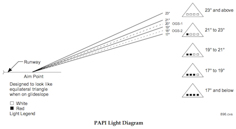
The Precision Approach Path Indicator (PAPI) lights are an electronic visual system that shows pilots if they are on the correct outer glide slope. PAPI lights are used at airports all over the world, but these have been modified for the unique configuration of the orbiter. A set of PAPI lights are at 7,500 feet (2,286 meters) and another at 6,500 feet (1,981 meters) to delineate an outer glide slope of between 18 and 20 degrees.
Ball-Bar Light System
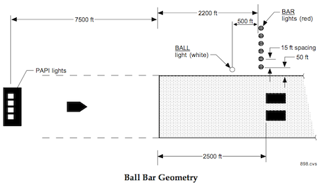
The Ball-Bar Light System is a visual reference to provide inner glide slope information. The bar lights are 24 red lamps in horizontal sets of four each. They are 2,200 feet (671 meters) from the runway threshold, and 300 feet (91 meters) from the first nominal touchdown point. Five hundred feet (152 meters) closer to the runway threshold are three white lights — the ball — at a higher elevation.
If the orbiter is above the glide slope of 1.5 degrees, the white lights will appear to be below the bar of red lights. If the vehicle is below the glide slope, the white lights will appear to be above the red lights. If the red and white lights are superimposed, the orbiter is on the correct glide slope.
Lighted distance markers show the crew the distance remain- ing to the end of the runway during landing and rollout. Just before touchdown, a flare or a pull-up maneuver brings the orbiter into its final landing configuration. Touchdown nominally is 2,500 to 2,700 feet (762 to 823 meters) beyond the runway threshold.
For night lights, the SLF has 16 powerful xenon lights, each of which produces up to 1 billion candlepower (1 billion candela). Flat- bed trailers hold eight lights, in two groups of four, at each end of the runway. To avoid blinding the crew, workers only turn on the lights at the end of the runway that will be behind the orbiter at landing.